Client Serial Ports
This page explains how to use your ShackConnect Client's serial ports to control server-side radios and other devices from external apps.
Prerequisites
- Connected ShackConnect Server
- Connected ShackConnect Client
- Configured server-side device exposing serial ports (e.g., a USB radio / rotator device)
Add and connect CLIENT SERIAL nodes
Go to SETUP and click the 'ADD NODE' button in the header bar.

In the panel that appears in the bottom of the screen, select CLIENT → CLIENT X → USB.
You should have CLIENT SERIAL nodes available. Each numbered CLIENT SERIAL node represents a specific serial port resource available on your Client.
If you do not see any nodes in this menu
- Check if the Client is connected.
- Check if you do not already have all available client resources placed in the canvas (you can click on them and hit the DELETE key or click the thrash can icon to restore them back into the ADD NODE menu).
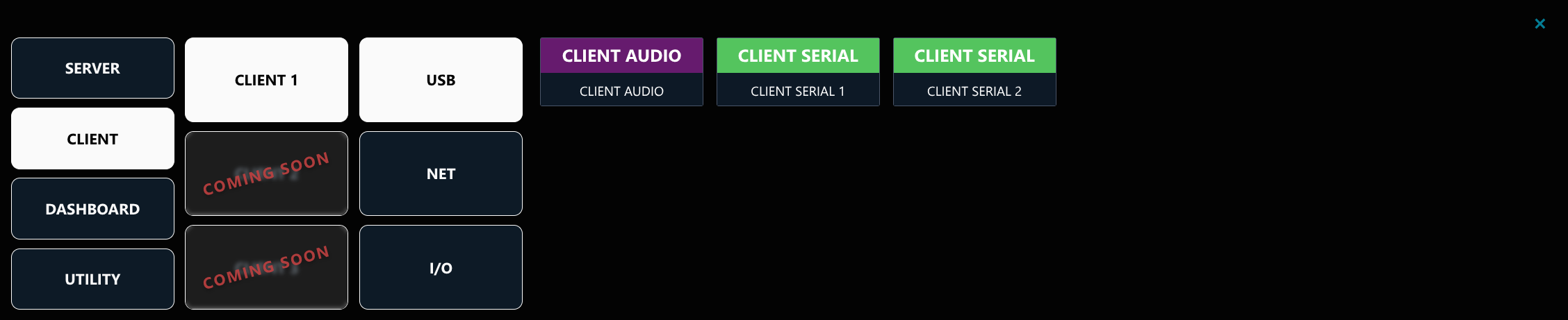
Drag a CLIENT SERIAL node into the canvas, then connect it to your server-side device by dragging from the arrow handle next to DATA.
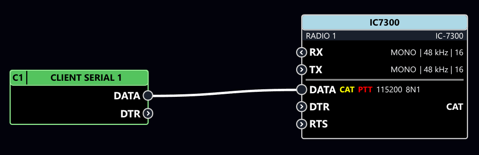
Click the RUN button in the header bar to start streaming, then open the serial port in your external application of choice.
Debug serial communication
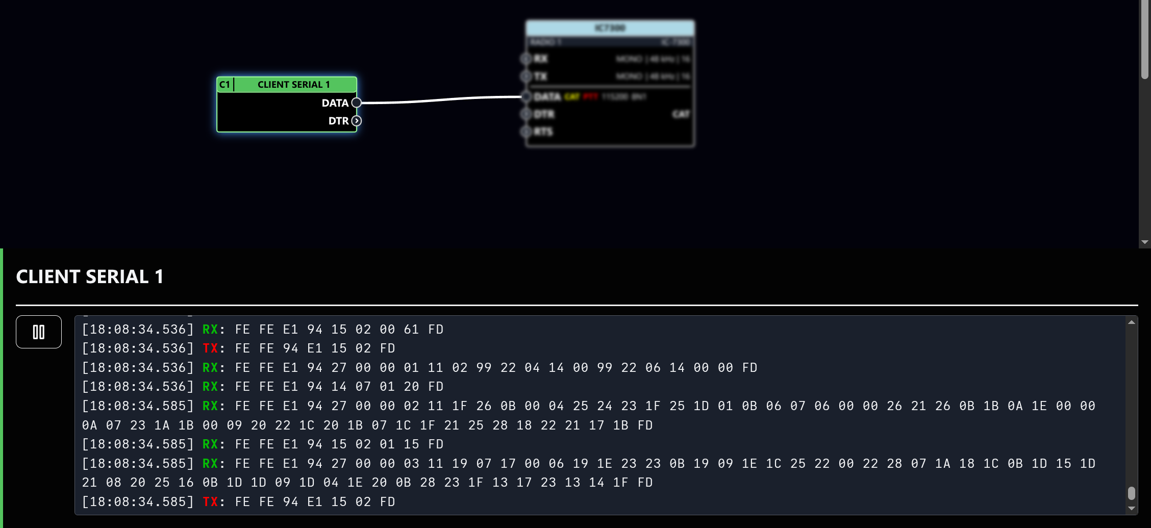
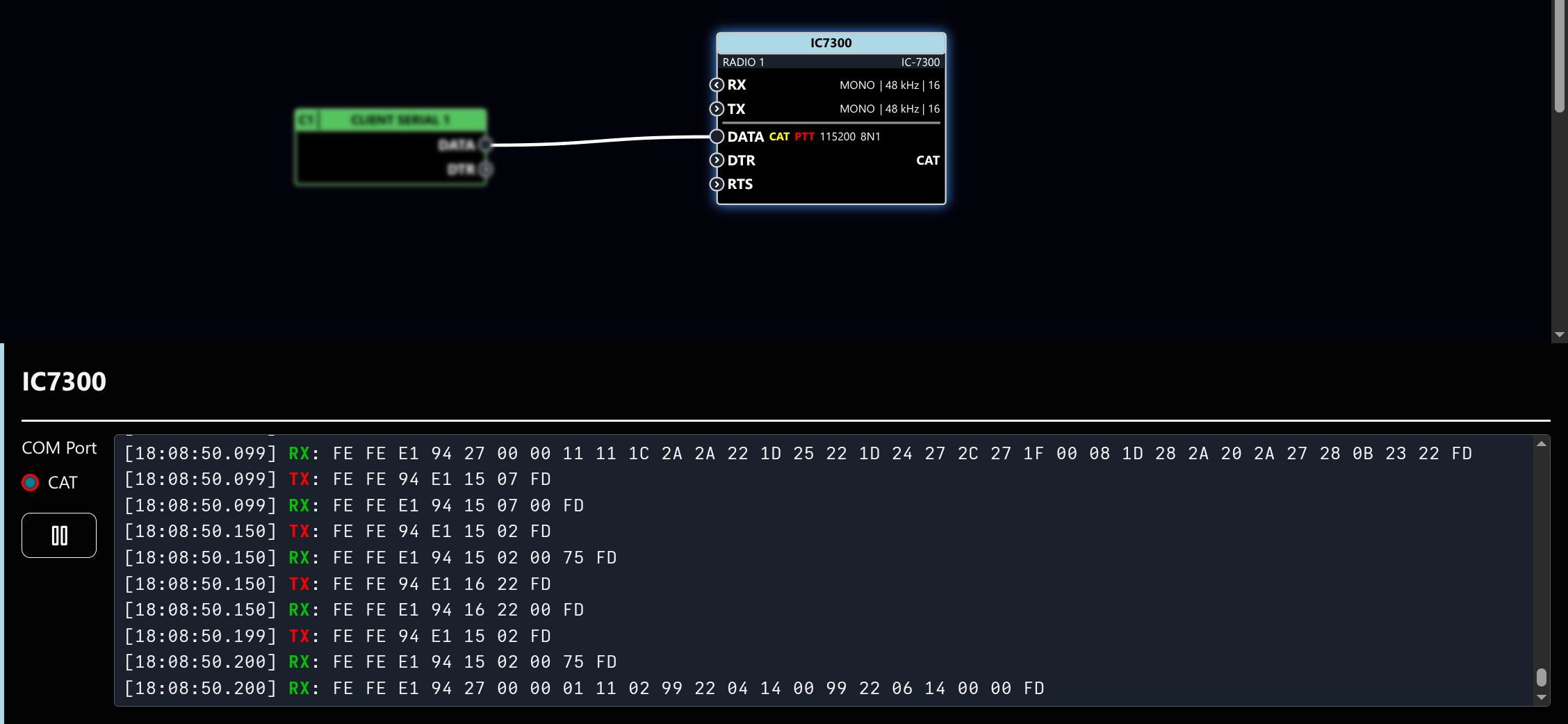
To verify that the communication between your device and the external app is working, you can click on the CLIENT SERIAL or the server-side device node WHILE STREAMING (RUN mode) to open the serial data log console.
Connect multiple applications to radio
You can connect multiple external applications to your server-side radio device concurrently, up to the number of serial ports available on your Client device. To do this, merge the serial ports with a MERGE CAT PORTS node (ADD NODE → UTILITY). You can also add a RADIO dashboard controller (ADD NODE → DASHBOARD) into the mix to control the radio from the dashboard concurrently with the external apps.
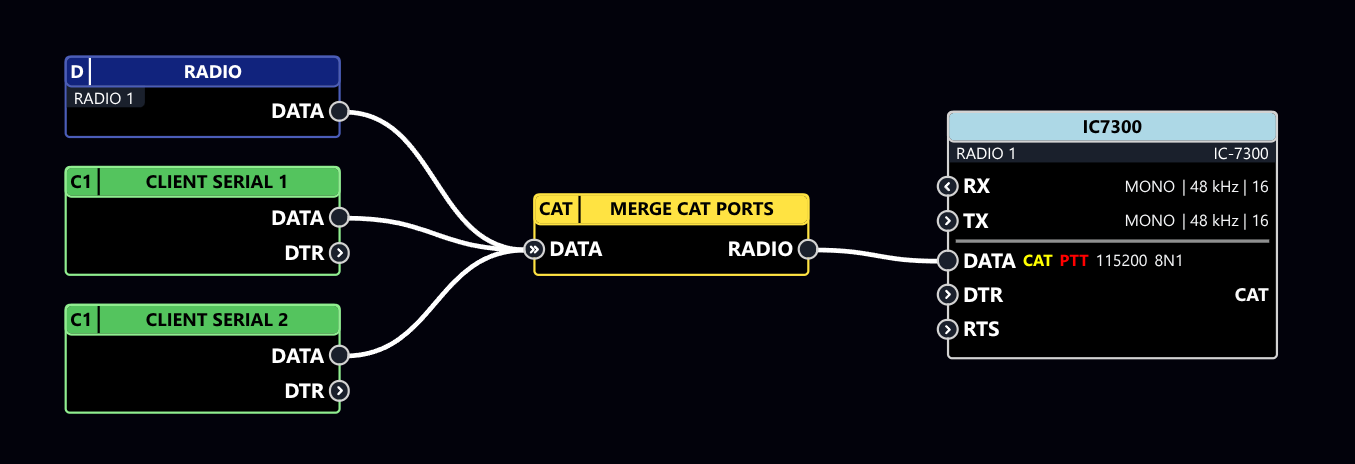
When using multiple applications with an Icom radio (CI-V protocol), you must ensure each application (external app as well as RADIO dashboard controller) is configured to use a unique controller CI-V address.
The controller address is a different address from the radio address. The radio address is typically assigned based on radio model, e.g. 94 for IC-7300. The controller address is typically defaulted to either E0 or 1 in most applications, and so must be changed to a unique value for each app to allow concurrent use.
Controller CI-V address for the RADIO controller can be changed by clicking the RADIO dashboard node in the SETUP view - top-left blue node in the picture.
If you were in streaming mode, you must first hit the STOP button in the header bar before you can edit the node wiring or configuration, or place and delete nodes.
You can remove existing nodes and wires from the profile by clicking on them, then hitting the DELETE key or clicking the thrash can icon.